Macropad: Difference between revisions
provided steps for platformio based firmware build and reprogramming step |
|||
| (6 intermediate revisions by 2 users not shown) | |||
| Line 1: | Line 1: | ||
== Assembly instructions: == | == Assembly instructions: == | ||
Assembly instructions can be found [https://docs.google.com/document/d/1evz1lOS-nTeEMei8WJlVfmJ6C-Dw2esytz5mxuN_9Ek/edit?usp=sharing here] | Assembly instructions can also be found in a printable form [https://docs.google.com/document/d/1evz1lOS-nTeEMei8WJlVfmJ6C-Dw2esytz5mxuN_9Ek/edit?usp=sharing here] | ||
Welcome! This guide will show the steps for making a macropad (specifically the macropad rev3) from one of our kits! | Welcome! This guide will show the steps for making a macropad (specifically the macropad rev3) from one of our kits! | ||
| Line 25: | Line 23: | ||
* We’ll start by installing the switches! Take a switch and align the 4 pins with the holes on the pcb, and press into place. Repeat for all three switches.[[File: | * | ||
** Next, we’ll solder these into place | * | ||
* | |||
* We’ll start by installing the switches! Take a switch and align the 4 pins with the holes on the pcb, and press into place. Repeat for all three switches. [[File:Switch_placement.png|400x400px]] | |||
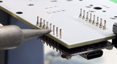
** Next, we’ll solder these into place | |||
** [[File:Soldering_switches.png]] | |||
*** To solder, put a little bit of solder into the hot iron, then rest the tip against both of the components you want to connect. After giving them a moment to heat up, slowly feed solder into the the components, until a cone shaped ring of solder surrounds the component. | |||
**** It's best to stop adding solder once the joint's sides have a concave shape; adding too much solder can lead to a brittle joint. | |||
*** For a full soldering tutorial, please watch this [https://www.youtube.com/watch?v=Qps9woUGkvI quick guide] | *** For a full soldering tutorial, please watch this [https://www.youtube.com/watch?v=Qps9woUGkvI quick guide] | ||
* Next, let’s install the rotary encoder | * Next, let’s install the rotary encoder | ||
*# First, make sure to bend all the pins until they’re sticking straight out. They sometimes get bent in shipping :/ | *# First, make sure to bend all the pins until they’re sticking straight out. They sometimes get bent in shipping :/ | ||
*# Now, place the encoder into the top left of the pcb. One side has 3 pins and the other has 2, so be sure you’re putting the encoder into the side of the pcb with the correct number of | *#* [[File:Bend pins.png|412x412px]] | ||
*# Now, place the encoder into the top left of the pcb. One side has 3 pins and the other has 2, so be sure you’re putting the encoder into the side of the pcb with the correct number of holes. Be careful to ensure that the encoder is sticking straight up (perpendicular to the circuit board). | |||
*#* [[File:Seating the encoder.png|321x321px]] | |||
*# Now, we can solder all 7 pins on the back of the encoder in place, just as we did for the switches! | *# Now, we can solder all 7 pins on the back of the encoder in place, just as we did for the switches! | ||
* At this point, we’re ready to solder in the controller. Start by putting 2 headers into the top right of the circuit board with the “long side” down. | * At this point, we’re ready to solder in the controller. Start by putting 2 headers into the top right of the circuit board with the “long side” down. | ||
*# Now, you can place the controller itself (the purple board) onto these headers. '''Make sure that the usb port faces away from the encoder!''' It should look like this: | ** [[File:Putting in headers.png|362x362px]] | ||
*# Now, solder all 16 points on this side. It should look something like this: '''''(though your board will have switches)''''' | **# Now, you can place the controller itself (the purple board) onto these headers. '''Make sure that the usb port faces away from the encoder!''' It should look like this: | ||
*# To fully connect the controller to the board, you’ll also need to solder the 16 headers on the other side, like so: | **#* [[File:Controller in place.png|285x285px]] | ||
**# Now, solder all 16 points on this side. It should look something like this: '''''(though your board will have switches)''''' | |||
**#* [[File:Soldered from top.png|417x417px]] | |||
**# To fully connect the controller to the board, you’ll also need to solder the 16 headers on the other side, like so: | |||
**#* [[File:Soldering back of controller.png|390x390px]] | |||
**#* Once you have all the connections soldered, the legs of the headers (on the back) should be trimmed. However, it's likely best to get firmware up and running beforehand, in case repairs need to be done. | |||
* Congratulations; that’s all the required soldering to get the board working! LEDs can also be added, but they are optional. | * Congratulations; that’s all the required soldering to get the board working! LEDs can also be added, but they are optional. | ||
* Now, you can follow the programming guide on the makerspace.cc wiki to get the code up and running! | * Now, you can follow the programming guide on the makerspace.cc wiki to get the code up and running! | ||
* | ** If you’d like to tweak or optimize the code, feel free! The source code can be found [https://github.com/Marshall-J2698/Makerpad here]. | ||
=== Adding LEDs === | |||
# To install LEDs, you'll need 3x 1.8mm LEDs and 3x 1000kΩ resistors. | |||
#* ''Note:'' If you're planning on using green LEDs, it's probably better to use 470Ω resistors; otherwise they might be a little dim | |||
# Start by bending the resistors to a U-shape; they should look like this | |||
#* [[File:Bend the resistors.png]] | |||
# Then install them into the holes next to each switch and solder them into place. | |||
#* Note that direction does not matter for resistor installation | |||
#** [[File:Resistor installation.png|433x433px]] | |||
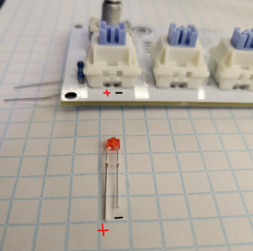
#Now, we'll add the LEDs; take care during this step, as the direction the LED is installed matters. The longer leg of the LED is positive and the shorter negative. | |||
##take an LED, and put it through the small hole in the front of your switch, so that it pokes out the two metal holes on the back of the pcb. | |||
##The longer leg should be facing the left side of the macropad. Look to the resistor image above to see the orientation the LEDs need to be installed. | |||
##*[[File:LED orientation.png|253x253px]] | |||
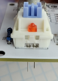
##*after installation, it should look like this: | |||
##*[[File:Installed LED.png]] | |||
##As before, these can be soldered into place from the back | |||
== Instructions for Programming the makerspace macropad == | == Instructions for Programming the makerspace macropad == | ||
<u>'''If you just made your macropad, you'll need to flash it with the firmware.'''</u> | <u>'''If you just made your macropad, you'll need to flash it with the firmware.'''</u> | ||
# download the [https:// | # download the [https://code.visualstudio.com/ Visual Studio Code] | ||
# | # Once installed, click on the extension menu (looks like 3-4 cubes stacked on top of eachother) | ||
# | # Search for platformio, then install! Select trust this author. This may take awhile, so be patient | ||
# | # In the mean time, go to the [https://github.com/Marshall-J2698/Makerpad github page], and download the repo | ||
#Back in VScode, click the new tab on the left that looks like an ant. you should be greeted with a home screen that has an option for opening an existing project. You want to find this, or a similar option, and use it to open the firmware folder from the repo you just cloned! | |||
#Once you do this, platformio will automatically start installing dependencies! Wait for these to be done, then plug in your board. | |||
#Hold down the zero button on the esp32 itself (it's the button next to the usb port labeled 0), then press the reset button. | |||
#Now, In the bottom row of VScode, press the right arrow button and wait for it to flash | |||
# | ##it may say "failed to upload"; this is usually not a big deal, so long as you saw the flashing progress bar a few seconds prior. | ||
#You should be good to go! | |||
'''<u>if you've already made, and flashed the firmware, there are only a few steps to reprogram:</u>''' | '''<u>if you've already made, and flashed the firmware, there are only a few steps to reprogram:</u>''' | ||
# press | # press the zero button on the esp32. This should stop keys from typing out null when pressed. | ||
# after ~5seconds, pressing key 1 should cause an address to be typed in; specifically 192.168.1.1 | # after ~5seconds, pressing key 1 should cause an address to be typed in; specifically 192.168.1.1 | ||
# Now, go to your wifi settings, and connect to the new network that's appeared (likely named macropad or macropad-config, unless you manually renamed it) | # Now, go to your wifi settings, and connect to the new network that's appeared (likely named macropad or macropad-config, unless you manually renamed it) | ||
## unless changed, the default password for this network is just "password" | |||
# open any web browser (while connected to this network) and type in the address 192.168.1.1 (or just press key 1) | # open any web browser (while connected to this network) and type in the address 192.168.1.1 (or just press key 1) | ||
# this should take you to the programming page! now, enter in what you want each key to do, and press submit! | # this should take you to the programming page! now, enter in what you want each key to do, and press submit! | ||
| Line 74: | Line 101: | ||
*Here's a comprehensive list of every availible special key: | *Here's a comprehensive list of every availible special key: | ||
**KEY_LEFT_CTRL KEY_LEFT_SHIFT KEY_LEFT_ALT KEY_LEFT_GUI KEY_RIGHT_CTRL KEY_RIGHT_SHIFT KEY_RIGHT_ALT KEY_RIGHT_GUI KEY_UP_ARROW KEY_DOWN_ARROW KEY_LEFT_ARROW KEY_RIGHT_ARROW KEY_MENU KEY_SPACE KEY_BACKSPACE KEY_TAB KEY_RETURN KEY_ESC KEY_INSERT KEY_DELETE KEY_PAGE_UP KEY_PAGE_DOWN KEY_HOME KEY_END KEY_NUM_LOCK KEY_CAPS_LOCK KEY_F1 KEY_F2 KEY_F3 KEY_F4 KEY_F5 KEY_F6 KEY_F7 KEY_F8 KEY_F9 KEY_F10 KEY_F11 KEY_F12 KEY_F13 KEY_F14 KEY_F15 KEY_F16 KEY_F17 KEY_F18 KEY_F19 KEY_F20 KEY_F21 KEY_F22 KEY_F23 KEY_F24 KEY_PRINT_SCREEN KEY_SCROLL_LOCK KEY_PAUSE | **KEY_LEFT_CTRL KEY_LEFT_SHIFT KEY_LEFT_ALT KEY_LEFT_GUI KEY_RIGHT_CTRL KEY_RIGHT_SHIFT KEY_RIGHT_ALT KEY_RIGHT_GUI KEY_UP_ARROW KEY_DOWN_ARROW KEY_LEFT_ARROW KEY_RIGHT_ARROW KEY_MENU KEY_SPACE KEY_BACKSPACE KEY_TAB KEY_RETURN KEY_ESC KEY_INSERT KEY_DELETE KEY_PAGE_UP KEY_PAGE_DOWN KEY_HOME KEY_END KEY_NUM_LOCK KEY_CAPS_LOCK KEY_F1 KEY_F2 KEY_F3 KEY_F4 KEY_F5 KEY_F6 KEY_F7 KEY_F8 KEY_F9 KEY_F10 KEY_F11 KEY_F12 KEY_F13 KEY_F14 KEY_F15 KEY_F16 KEY_F17 KEY_F18 KEY_F19 KEY_F20 KEY_F21 KEY_F22 KEY_F23 KEY_F24 KEY_PRINT_SCREEN KEY_SCROLL_LOCK KEY_PAUSE | ||
'''<u>Legacy steps for reprogramming</u>''' - As of april 2026, we have moved our firmware to Platformio build system, as it makes for a much more repeatable development and usage experience. If you would like to use the old arduino code and procedure, feel free to look through old commits in the github, and follow the tutorial below. | |||
# download the [https://www.arduino.cc/en/software arduino IDE] | |||
# In the arduino IDE, go to tools->boards->board manager. Then search esp32 and install the library made by arduino | |||
# Then go to tools->manage libraries then install the following: | |||
## ArduinoJson | |||
## StringSplitter | |||
# press select board, esp32, and select esp32S2 Dev Module | |||
# go to the [https://github.com/Marshall-J2698/Makerpad github page], and download all the files. Now, open the ino file in the arduino program (you may need to do some renaming-the IDE should do this for you). | |||
#Now plug in your board, and press the two reset buttons that are on the ESP32 (the purple board) itself; they're located near the usb port. If you're using the makerspace case, there's a hole on the top of the case and next to the usb port. Specifically, you want to hold the top button for ~2s and then press the other key once. | |||
#Go to tools->port->then select the one with esp32 | |||
#now press the upload button! (it's the right-facing arrow, in the top left) | |||
'''<u>if you've already made, and flashed the firmware, there are only a few steps to reprogram:</u>''' | |||
# press down key 1 (the left key) and the encoder knob at the same time, until key 1 stops sending keypresses | |||
# after ~5seconds, pressing key 1 should cause an address to be typed in; specifically 192.168.1.1 | |||
# Now, go to your wifi settings, and connect to the new network that's appeared (likely named macropad or macropad-config, unless you manually renamed it) | |||
# open any web browser (while connected to this network) and type in the address 192.168.1.1 (or just press key 1) | |||
# this should take you to the programming page! now, enter in what you want each key to do, and press submit! | |||
[[Category:Projects]] | |||
[[Category:Soldering]] | |||
[[Category:Programming]] | |||
[[Category:SimpleProjects]] | |||
Latest revision as of 15:51, 3 April 2026
Assembly instructions:
Assembly instructions can also be found in a printable form here
Welcome! This guide will show the steps for making a macropad (specifically the macropad rev3) from one of our kits!
Your kit should contain the following:
- The ESP32S2-This is the microcontroller, which actually talks to your computer
- The circuit board-This is what connects all the components together, enabling the whole thing to work
- 3x keyswitches-These are what you actually press to make key inputs
- Rotary encoder and knob-allows for volume control
- 3x 1K ohm resistors-Used to get proper current to LEDs. Only required if you want to install LEDs
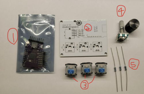
Parts list!

- We’ll start by installing the switches! Take a switch and align the 4 pins with the holes on the pcb, and press into place. Repeat for all three switches.
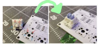
- Next, we’ll solder these into place
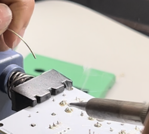
- To solder, put a little bit of solder into the hot iron, then rest the tip against both of the components you want to connect. After giving them a moment to heat up, slowly feed solder into the the components, until a cone shaped ring of solder surrounds the component.
- It's best to stop adding solder once the joint's sides have a concave shape; adding too much solder can lead to a brittle joint.
- For a full soldering tutorial, please watch this quick guide
- To solder, put a little bit of solder into the hot iron, then rest the tip against both of the components you want to connect. After giving them a moment to heat up, slowly feed solder into the the components, until a cone shaped ring of solder surrounds the component.
- Next, let’s install the rotary encoder
- First, make sure to bend all the pins until they’re sticking straight out. They sometimes get bent in shipping :/
- Now, place the encoder into the top left of the pcb. One side has 3 pins and the other has 2, so be sure you’re putting the encoder into the side of the pcb with the correct number of holes. Be careful to ensure that the encoder is sticking straight up (perpendicular to the circuit board).
- Now, we can solder all 7 pins on the back of the encoder in place, just as we did for the switches!
- First, make sure to bend all the pins until they’re sticking straight out. They sometimes get bent in shipping :/
- At this point, we’re ready to solder in the controller. Start by putting 2 headers into the top right of the circuit board with the “long side” down.
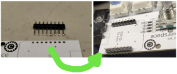
- Now, you can place the controller itself (the purple board) onto these headers. Make sure that the usb port faces away from the encoder! It should look like this:
- Now, solder all 16 points on this side. It should look something like this: (though your board will have switches)
- To fully connect the controller to the board, you’ll also need to solder the 16 headers on the other side, like so:
- Once you have all the connections soldered, the legs of the headers (on the back) should be trimmed. However, it's likely best to get firmware up and running beforehand, in case repairs need to be done.
- Now, you can place the controller itself (the purple board) onto these headers. Make sure that the usb port faces away from the encoder! It should look like this:
- Congratulations; that’s all the required soldering to get the board working! LEDs can also be added, but they are optional.
- Now, you can follow the programming guide on the makerspace.cc wiki to get the code up and running!
- If you’d like to tweak or optimize the code, feel free! The source code can be found here.


Adding LEDs
- To install LEDs, you'll need 3x 1.8mm LEDs and 3x 1000kΩ resistors.
- Note: If you're planning on using green LEDs, it's probably better to use 470Ω resistors; otherwise they might be a little dim
- Start by bending the resistors to a U-shape; they should look like this
- Then install them into the holes next to each switch and solder them into place.
- Note that direction does not matter for resistor installation
- Note that direction does not matter for resistor installation
- Now, we'll add the LEDs; take care during this step, as the direction the LED is installed matters. The longer leg of the LED is positive and the shorter negative.
- take an LED, and put it through the small hole in the front of your switch, so that it pokes out the two metal holes on the back of the pcb.
- The longer leg should be facing the left side of the macropad. Look to the resistor image above to see the orientation the LEDs need to be installed.
- after installation, it should look like this:
- As before, these can be soldered into place from the back


Instructions for Programming the makerspace macropad
If you just made your macropad, you'll need to flash it with the firmware.
- download the Visual Studio Code
- Once installed, click on the extension menu (looks like 3-4 cubes stacked on top of eachother)
- Search for platformio, then install! Select trust this author. This may take awhile, so be patient
- In the mean time, go to the github page, and download the repo
- Back in VScode, click the new tab on the left that looks like an ant. you should be greeted with a home screen that has an option for opening an existing project. You want to find this, or a similar option, and use it to open the firmware folder from the repo you just cloned!
- Once you do this, platformio will automatically start installing dependencies! Wait for these to be done, then plug in your board.
- Hold down the zero button on the esp32 itself (it's the button next to the usb port labeled 0), then press the reset button.
- Now, In the bottom row of VScode, press the right arrow button and wait for it to flash
- it may say "failed to upload"; this is usually not a big deal, so long as you saw the flashing progress bar a few seconds prior.
- You should be good to go!
if you've already made, and flashed the firmware, there are only a few steps to reprogram:
- press the zero button on the esp32. This should stop keys from typing out null when pressed.
- after ~5seconds, pressing key 1 should cause an address to be typed in; specifically 192.168.1.1
- Now, go to your wifi settings, and connect to the new network that's appeared (likely named macropad or macropad-config, unless you manually renamed it)
- unless changed, the default password for this network is just "password"
- open any web browser (while connected to this network) and type in the address 192.168.1.1 (or just press key 1)
- this should take you to the programming page! now, enter in what you want each key to do, and press submit!
A few notes on configuring the keys:
- With the default firmware, the 3 main keys are set up to do basic keyboard functions and the volume knob does media controls. You can't mix and match functionality between these two groups without manually editing the firmware
- to input modifiers (ie. shift, control, alt), you have to use a strange format
- Shift = KEY_LEFT_SHIFT, Alt = KEY_LEFT_ALT, Control = KEY_LEFT_CTRL
- put whatever modifiers you want at the start of your macro, and seperate them with "+++" from the rest of your input
- for example to send "ctrl+shift+t" I would input: KEY_LEFT_CTRL+++KEY_LEFT_SHIFT+++t
- modifiers must be at the start of the sequence: KEY_LEFT_CTRL+++t+++KEY_LEFT_SHIFT will not work
- Here's a comprehensive list of every availible special key:
- KEY_LEFT_CTRL KEY_LEFT_SHIFT KEY_LEFT_ALT KEY_LEFT_GUI KEY_RIGHT_CTRL KEY_RIGHT_SHIFT KEY_RIGHT_ALT KEY_RIGHT_GUI KEY_UP_ARROW KEY_DOWN_ARROW KEY_LEFT_ARROW KEY_RIGHT_ARROW KEY_MENU KEY_SPACE KEY_BACKSPACE KEY_TAB KEY_RETURN KEY_ESC KEY_INSERT KEY_DELETE KEY_PAGE_UP KEY_PAGE_DOWN KEY_HOME KEY_END KEY_NUM_LOCK KEY_CAPS_LOCK KEY_F1 KEY_F2 KEY_F3 KEY_F4 KEY_F5 KEY_F6 KEY_F7 KEY_F8 KEY_F9 KEY_F10 KEY_F11 KEY_F12 KEY_F13 KEY_F14 KEY_F15 KEY_F16 KEY_F17 KEY_F18 KEY_F19 KEY_F20 KEY_F21 KEY_F22 KEY_F23 KEY_F24 KEY_PRINT_SCREEN KEY_SCROLL_LOCK KEY_PAUSE
Legacy steps for reprogramming - As of april 2026, we have moved our firmware to Platformio build system, as it makes for a much more repeatable development and usage experience. If you would like to use the old arduino code and procedure, feel free to look through old commits in the github, and follow the tutorial below.
- download the arduino IDE
- In the arduino IDE, go to tools->boards->board manager. Then search esp32 and install the library made by arduino
- Then go to tools->manage libraries then install the following:
- ArduinoJson
- StringSplitter
- press select board, esp32, and select esp32S2 Dev Module
- go to the github page, and download all the files. Now, open the ino file in the arduino program (you may need to do some renaming-the IDE should do this for you).
- Now plug in your board, and press the two reset buttons that are on the ESP32 (the purple board) itself; they're located near the usb port. If you're using the makerspace case, there's a hole on the top of the case and next to the usb port. Specifically, you want to hold the top button for ~2s and then press the other key once.
- Go to tools->port->then select the one with esp32
- now press the upload button! (it's the right-facing arrow, in the top left)
if you've already made, and flashed the firmware, there are only a few steps to reprogram:
- press down key 1 (the left key) and the encoder knob at the same time, until key 1 stops sending keypresses
- after ~5seconds, pressing key 1 should cause an address to be typed in; specifically 192.168.1.1
- Now, go to your wifi settings, and connect to the new network that's appeared (likely named macropad or macropad-config, unless you manually renamed it)
- open any web browser (while connected to this network) and type in the address 192.168.1.1 (or just press key 1)
- this should take you to the programming page! now, enter in what you want each key to do, and press submit!